Commercial HVAC-R Products: Air-Conditioning, Refrigeration & Heat Pumps
We design, supply, install, and maintain multi-split/dual-zone, ducted and cassette air-conditioning, commercial refrigeration (cold & freezer rooms, walk-ins, display cabinets), and energy-saving heat-pump hot-water systems—engineered for uptime, energy efficiency, and compliance across South Africa.
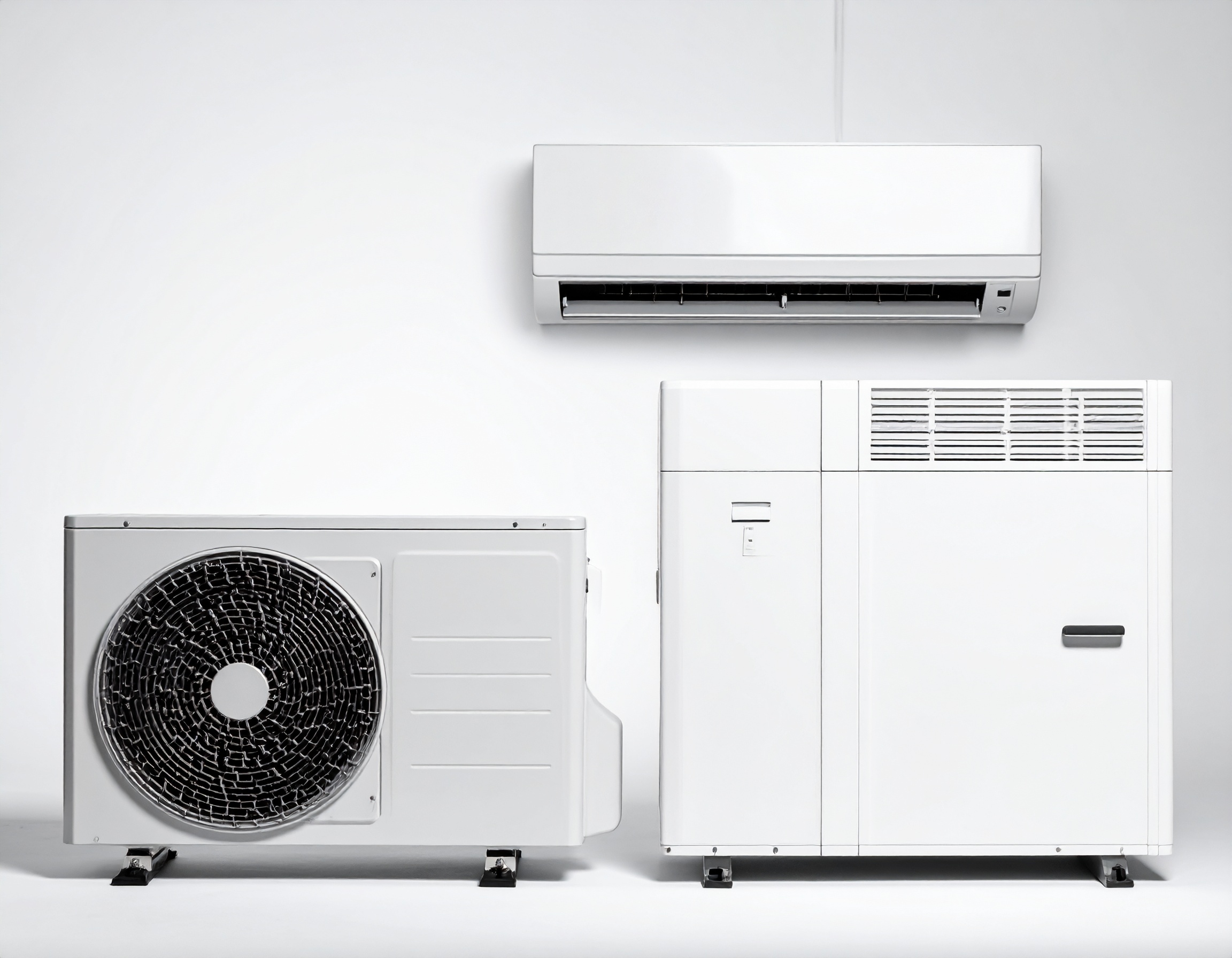
Air-Conditioning Systems
Key Benefits
- Right-sized multi-split, dual-zone, ducted & cassette for commercial spaces
- Inverter efficiency and low noise for steady comfort & lower kWh
- Optional BMS/Modbus control for central scheduling & monitoring
Technical Highlights
- 2–8 indoor units per outdoor (model dependent)
- Long line-set options, high-lift drain pumps, coastal-grade coils
- 230V/1-ph and 400V/3-ph, R32/R410A (per model & compliance)
Right-sized commercial air-conditioning for offices, retail, hospitality, healthcare, and light industrial—covering multi-split, dual-zone, ducted, and cassette systems with inverter efficiency and quiet operation.
Key Features
- System Types: multi-split/dual-zone, ceiling cassette, slim ducted, wall splits, rooftop package (where suitable).
- Controls: wired/wireless room stats, central schedulers, BMS integration (Modbus/BACnet gateways), lockouts & setpoint bands.
- Efficiency & Comfort: inverter compressors, after-hours setback, low-noise indoor units, coastal/anti-corrosion options.
Design & Sizing
- Room-by-room heat load (sensible/latent), occupancy, internal gains, glazing & orientation.
- Choose indoor type per space (cassettes for open-plan, ducted for discreet/quiet rooms, wall units for quick installs).
- Confirm electrical (1-ph/3-ph), line lengths, level differences; follow manufacturer rules for branches, traps, insulation.
Applications
- Offices/boardrooms, retail & restaurants, clinics/education, small warehouses & IT rooms.
Maintenance (SLAs)
Filters/coils/drains, leak checks, diagnostics, controller verification; priority call-outs and reporting.
Why Ventilation Matters
Fresh air reduces CO₂ and VOC build-up, supports comfort and productivity, and protects temperature-critical spaces by managing humidity and pressure.
Systems We Provide
- Fresh-Air Supply (FAU): tempered outdoor air ducted to zones or to ducted AC return.
- HRV/ERV: heat/energy recovery to cut kWh while meeting fresh-air targets.
- Extract Systems: bathrooms, kitchens, store rooms, and point extraction for odours/particulates.
Design & IAQ
- Airflow rates set from occupancy & floor area; target comfortable CO₂ levels and humidity control.
- Filtration: G4–MERV/M5–MERV for general areas, higher grades where hygiene needs it; allow service access.
- Pressure Strategy: neutral/slight-positive for occupied zones; balanced extract where required.
- Noise & Location: lined duct, low-SPL fans, weather-protected intakes/exhausts.
Integration with AC
- Mix FAU with ducted AC or deliver directly to space; interlock fans with AC schedules; monitor via BMS where installed.
Maintenance (SLAs)
- Filter changes/cleans, belt & fan checks, coil hygiene on tempering coils, damper function tests, airflow re-verification.
Good Use Cases
Open-plan offices & classrooms (CO₂ control), clinics & kitchens (extract + make-up air), retail floors (comfort + odour control).
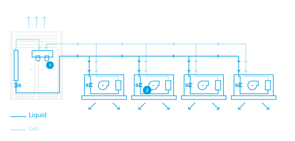
VRF / VRV (Two-Pipe) Heat-Pump Schematic — How it works
A single outdoor unit modulates refrigerant flow to multiple indoor fan-coil units. All zones run in the same mode (cool or heat) at a time. The dark line = liquid and the light line = gas; refrigerant is distributed along the main header and branched to each indoor. Each indoor unit has its own electronic expansion valve (EEV) to control capacity, while the outdoor inverter compressor varies output to match total load.
Callouts in the diagram
- Outdoor unit & controls – inverter compressor, heat exchanger, and control valves manage total capacity and mode.
- Indoor fan-coil with EEV – meters refrigerant to the coil for precise room control; arrows show conditioned air supply.
Design notes (quick)
For simultaneous heating & cooling, use a heat-recovery (3-pipe) system with branch selector (not shown here).
Keep branch tees within the manufacturer’s geometry; respect max pipe lengths/level differences.
Nitrogen purge while brazing, insulate liquid/gas lines correctly, add oil traps on tall risers.

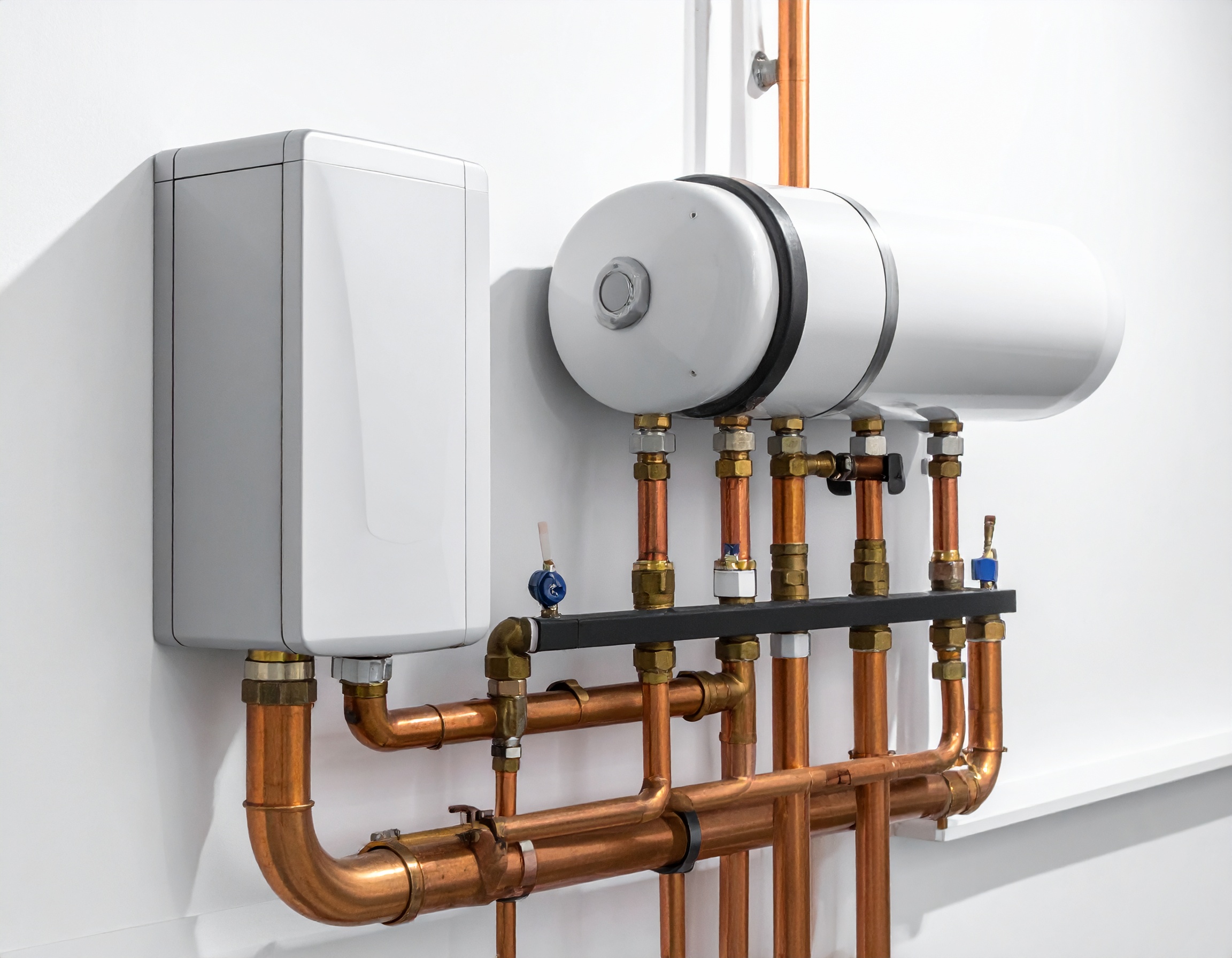
Energy-Saving Heat-Pump Geysers & Plant Integrations
Business Benefits
- High-COP hot-water generation to cut energy costs
- Consistent supply for hotels, gyms, kitchens & multi-site facilities
- Tariff-friendly scheduling and integration with existing plant
System Details
- Standalone heat-pump geysers or cylinder integrations
- Cascade options for large demand profiles
- Noise-managed indoor/outdoor modules with condensate control
High-COP heat-pump hot-water systems that cut kWh versus electric elements while keeping supply stable for hotels, gyms, kitchens, hostels, and multi-site facilities.
System Options
- Standalone heat-pump geysers (all-in-one or split condenser/evaporator).
- Cylinder integrations with existing storage tanks (buffer or primary).
- Plant integrations with multiple HP units in cascade for large demand.
Performance & Control
- COP typically 2.5–4.0 (site & model dependent).
- Smart scheduling/tariff windows, anti-legionella pasteurisation cycles, and temperature setpoint control via onboard or BMS.
- Quiet operation options; weather-protected housings for outdoor install.
Maintenance (SLAs)
Coil/fin cleaning, condensate management, anode inspection, sensor & valve checks, performance tests; spares and rapid response.
What “heat recovery” means
Capturing waste heat from cooling equipment and using it to pre-heat or fully heat domestic hot water (DHW) or process water—reducing compressor runtime on dedicated water-heating plant.
Common recovery sources
- VRF/VRV heat-recovery systems: desuperheater or dedicated DHW heat-recovery module takes compressor discharge heat.
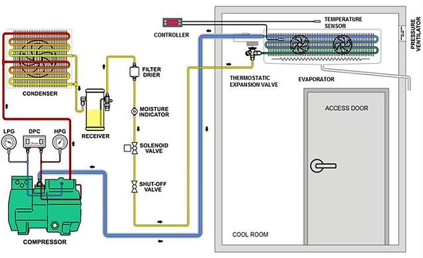
- Commercial refrigeration (cold rooms / display cases): hot-gas heat reclaim via a plate or coaxial heat exchanger placed upstream of the condenser.
- Chiller/AC plants: condenser-water or rejected heat streams repurposed for DHW pre-heat.
Integration patterns
- Pre-heat + Heat-Pump finish: recover heat lifts water (e.g., 20–40 °C) → heat pump tops up to setpoint (e.g., 60 °C).
- Parallel boost: when recovery is available, reduce HP load; HP resumes when recovery falls short.
- Seasonal / demand-based: prioritise recovery when cooling load is present; default to HP in low-cooling periods.
Controls & safety
- Prioritise recovery first, with automatic switchover to heat pump when recovery temp or flow is insufficient.
- Fit mixing (TMV) anti-scald valves; maintain pasteurisation cycles (≥60 °C) for legionella risk management.
- Instrument with supply/return sensors, flow switch, and BMS points (run status, temps, energy, alarms).
Design notes
- Size the HX and primary pump for expected discharge heat and target ΔT; insulate all hot lines.
- Ensure no condensing in compressors (follow OEM reclaim limits, superheat requirements).
- Provide bypass around the recovery HX for maintenance and low-load conditions.
- In supermarkets/hotels, recovery can cover a large share of DHW during trading hours.
Where it shines
Hotels, gyms, laundries, restaurant kitchens, supermarkets—sites with coincident cooling + hot-water demand.
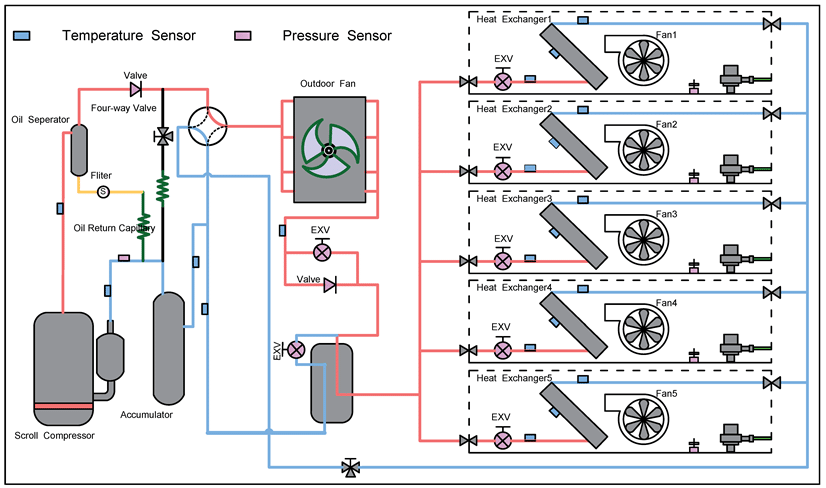
VRF Heat-Pump System — How it Works
This schematic shows a variable-refrigerant-flow (VRF) air-conditioning heat-pump serving multiple indoor coils. An inverter scroll compressor drives refrigerant through a four-way reversing valve so the system can cool or heat. The outdoor coil (with fan) acts as the condenser in cooling and the evaporator in heating. Refrigerant is distributed to each indoor heat exchanger via headers; every indoor has its own electronic expansion valve (EXV) for precise capacity control. Temperature (blue) and pressure (pink) sensors feed the controller for stable operation, superheat management, and fault monitoring.
Key callouts
- Compressor & oil management: scroll compressor with oil separator and accumulator for reliability.
- Reversing valve: switches flow for heating vs cooling modes.
- Indoors: multiple fan-coil units with EXVs; fans move room air across the coil to deliver conditioned air.
Design notes
For simultaneous heat & cool, add a heat-recovery branch-selector module (not shown here) and integrate points to BMS where required.
Respect manufacturer limits on piping lengths/level differences and branch geometry.
Provide condensate management at indoor units and adequate service clearances.